This is the third chapter documenting the epic construction of the John-Henry Class Rocketship named the SRS Imagination. Please be sure to check out chapters one and two to learn about the entire process from the beginning.
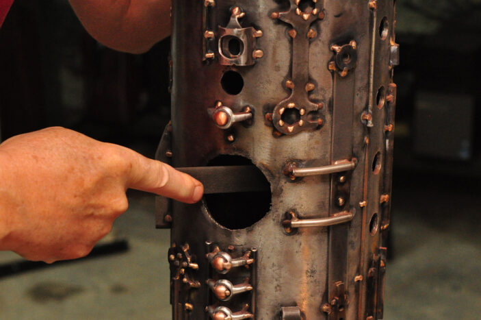
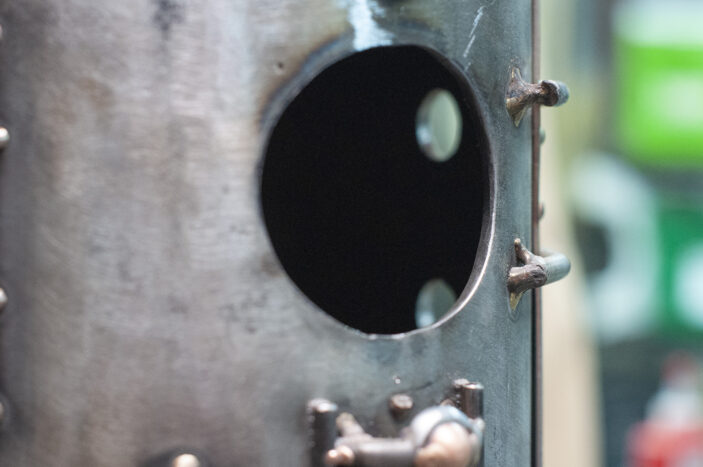
The SCUBA tanks that are used to construct the fuselage of the Imagination have a wall thickness of 3/8″. Years ago when I first began construction, I used a hand-held plasma cutter to cut a freehand circle, with a notion to round it out later by employing some indeterminate and clever means. While I’m somewhat familiar with the operation of milling machines and lathes, I tend not to use them much, as I prefer to work things by hand. In this case I may have been better off using a machine, but there weren’t any around when it was go-time, so it came down to working with a fresh hand-file. It took a fair number of hours and made for some sore forearms by day’s end, but it got the job done.
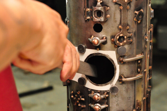
I began with a template made from paper held on with magnets, which attracted a lot of iron filings, as you can see in this image.
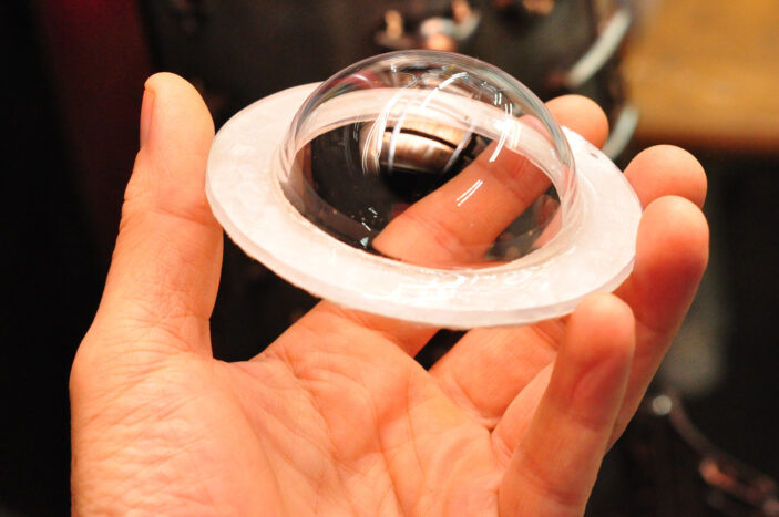
Here’s the polycarbonate dome – it was custom made up in the great state of Maine by EZ Tops. It took about four weeks for it to be manufactured and shipped to me. I ordered two of them, as it’s nice to have a backup if anything goes wrong, either during construction or ‘out in space’. Constructing this rocketship put me in a lot of unfamiliar territory, which is exciting for me as an artist. Experience has taught me that it’s nice to have insurance against errors. I wasn’t sure how I’d feel about working with any material that wasn’t metal, but it turns out polycarbonate has excellent work-ability. It can be hack-sawed, ground, drilled, tapped, and hand-filed without cracking. I think it’s a beautiful material as well, and not as easily scratched as I thought. Still, I proceeded with extreme caution.
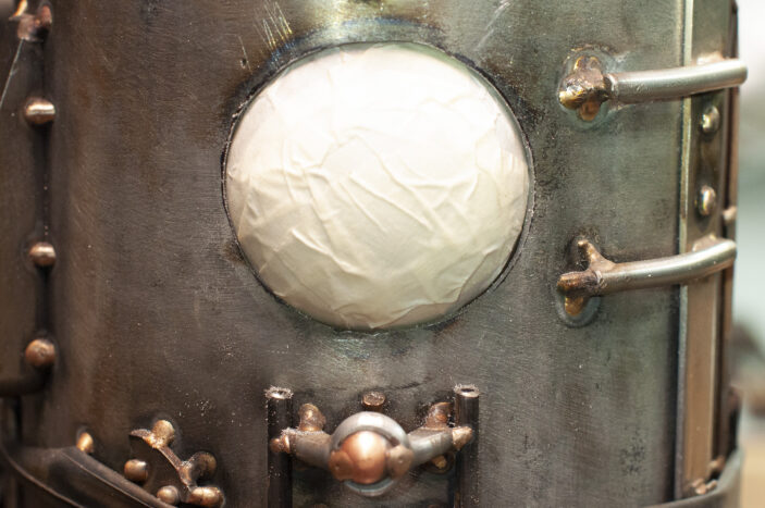
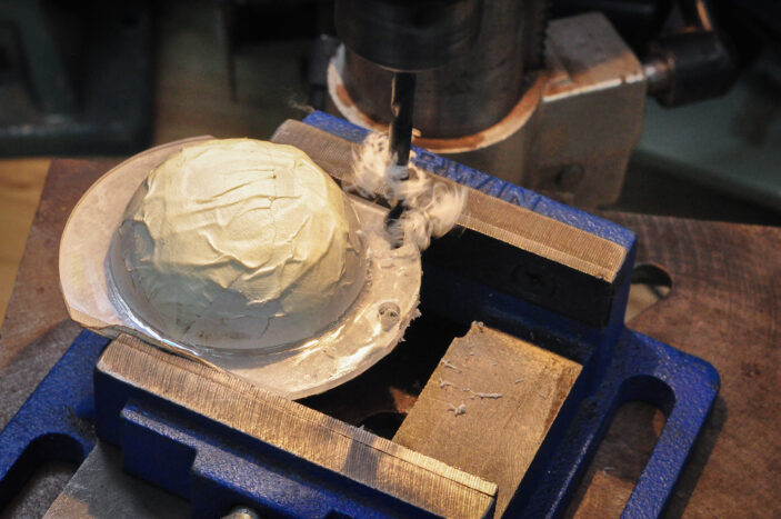
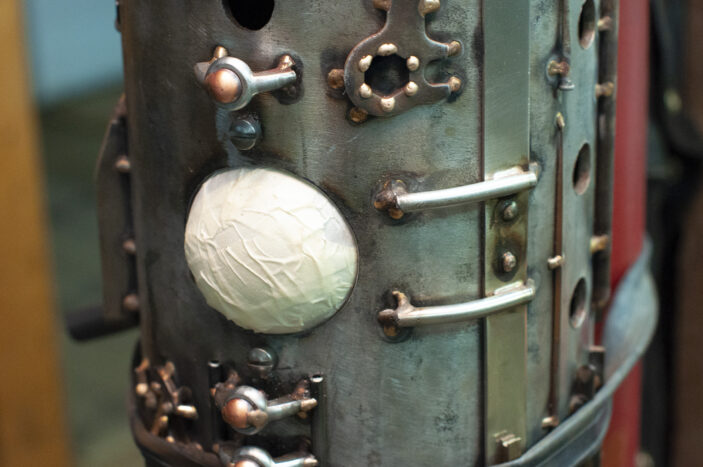
By covering the portal dome window with a thick layer of masking tape, I was able to use it to check fit-up as I got close to the correct dimensions. I used to look at the gaps when filing, now I know that it’s the spots that are touching that are the things to concentrate on.
In order to have to dome fit snugly the wall must be tapered to match the curvature of the dome. The hole is also slightly ovoid, as I’m fitting a spherical shape to a curved surface. While it’s hardly noticeable to the viewer, it’s important to consider as a builder. I think this may have been tricky from a machinist’s point of view, at least with my limited skill-set, unless they happen to make 2.25″ ball end-mills. I bet they are extremely cost-prohibitive, if they exist at all.
The flange on the dome was wide enough to interfere with the window settling into the inside curvature of the fuselage, and therefore needed to be removed on the sides. Holes were then drilled at the twelve o’clock and six o’clock position, for the dome to be bolted to the fuselage.
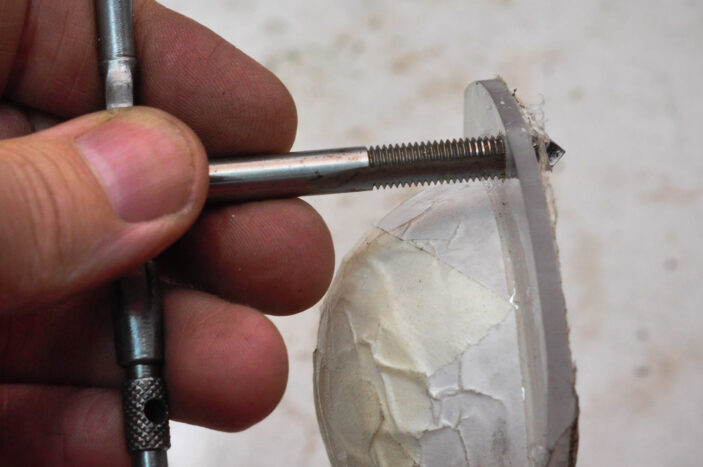
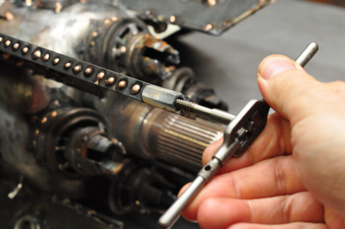
One of the nice thing about being a junk metal sculptor is that the donations often include working tools. While this tap handle and tap were given to me to use as pieces in my art, I’m able to use them for their intended purpose.
I find the chips to be reminiscent of the workings of a woodpecker.
Here’s the portal window bolted in. I’m satisfied with the fit-up. Time to take the tape off!
Now that the portal window was ready for installation I needed to complete the rest of the command module. It was a lot of fun choosing the parts for the cramped space in this tiny room.
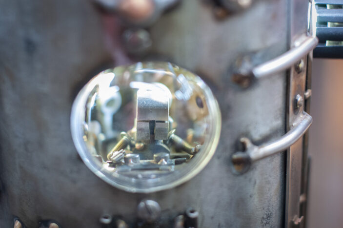
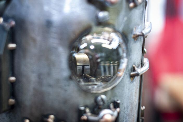
I had to see what it’d look like to have the command module installed, so I used a flashlight to illuminate the inside and put things together temporarily. I’m very pleased with how the dome distorts the interior like a lens.
Here you can see some of the details of the command modules vague controls. The distortion adds to the mystery of their function.
For this rocketship, the portal is the focus of the piece. I feel like there’s a tiny story in the making in there.
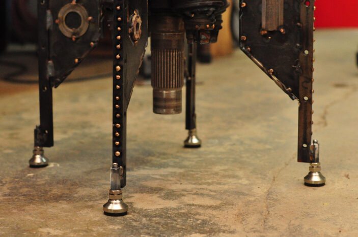
Anyone who’s lived in an old building knows that floors are rarely level, nor are they flat. I wanted my rocketship to be able to stand perfectly vertical, and in order to make that possible, there’s a need for adjustable ‘landing gear’. Years ago I bought some stainless steel adjustable furniture pads – and after I got them to the shop I remember saying to myself “these are perfect!”, followed by “wait! I wanted the table to be on casters!”. Turns out I needed them after all, albeit for something much more exciting than my desk. All that was needed to mount them to the fins of the rocketship was for me to weld some coupling nuts to the bases.
Distortion is an inherent side effect of welding, so these coupling nuts needed to be chased with a tap. Again, I had the right size thanks to the the plentiful scrap supply. Folks have been very kind to me when it comes to supplying me with great metal: It would be impossible for me to create on this level without that generosity.
I wound up removing the rubber at the bases of the feet. They started to come off on their own when I was moving the rocketship around the shop to work on it. I also found the lock-nuts to be obtrusive and not helpful, so I opted out of using them as well.
Once the ‘landing gear’ was installed, the SRS Imagination became very stable. Again, this is an early photo, so imagine it without the rubber bottoms and extra nut if you can.
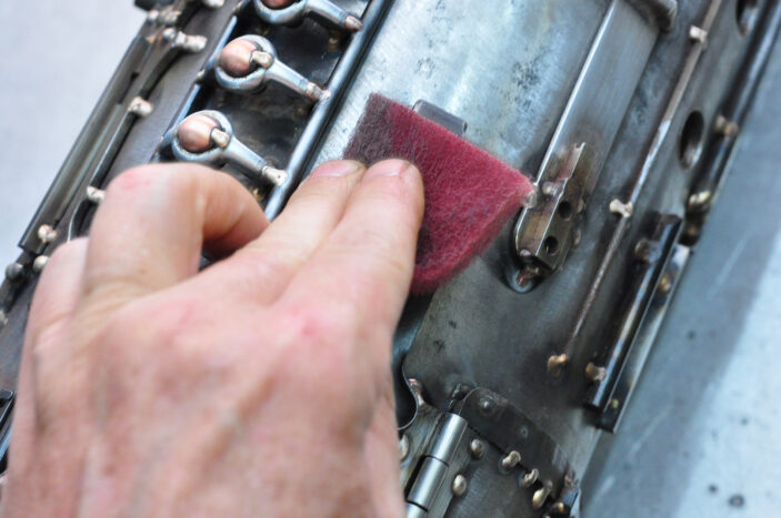
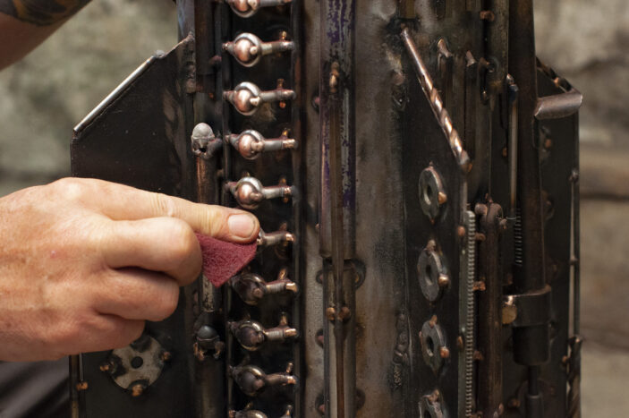
At this stage (no pun intended) of the rocket’s exterior, it was down to the small details, specifically the finish work before the clear lacquer. While my technique can vary, I often prefer to put a satin finish on my metalwork, so I typically use a very fine grade Scotch-Brite pad to remove the oxidization. This is the same technique used to finish the titanium bicycle tubing at Seven Cycles – to whom I owe so much from the support I’ve been receiving for over twenty years, as well as the skill-set I have accrued from the master craftspeople that trained me there. Unlike the titanium, which is finished along with the circumference of the tubing, I scrubbed most of the rocketship in a vertical direction, as I wanted to give the feeling of upwards movement. Subtleties such as these are important in a work of art, even if they aren’t consciously noticed.
The copper on the ladder rivets, however, are brushed in a horizontal orientation for contrast, and to give a more stable, ladder-like feeling.
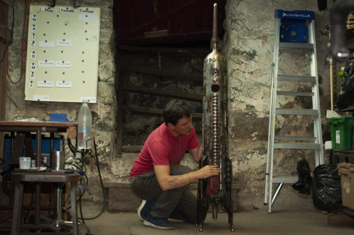
My client commented that me working on this cool thing in the basement was a bit like Tony Stark in the first Iron Man movie. I find the environment to be very cozy!
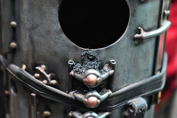
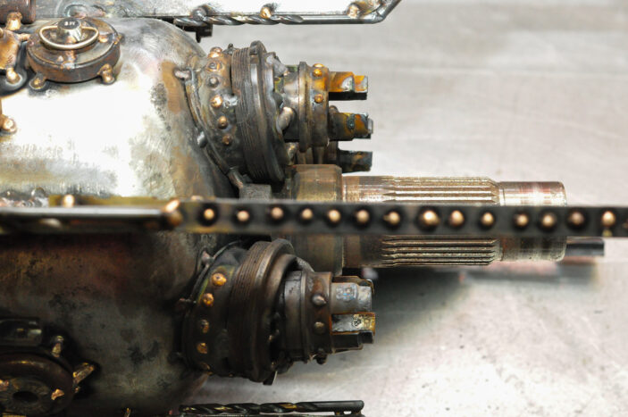
In the case of the mighty rocket boosters, I wanted to make them look like they’ve been used a lot. By using the welding torch to singe the metal, I was able to get the look I was going for.
Now that’s a rocketship that looks like it’s been around the galaxy once or twice!
Next step: finishing up the interior!
Related Posts
Constructing a John Henry Class Rocketship: Stage One
Constructing a John Henry Class Rocketship: Stage Two
Constructing a John Henry Class Rocketship: Stage Four
